REAL TIME X-RAY INSPECTION SYSTEMS
CONTENTS
1. INTRODUCTION
2. SYSTEM COMPONENTS
3. TECHNICAL DETAILS OF THE SYSTEM COMPONENTS
4. INITIAL ADJUSTMENT AND INSPECTION PROCESS
INTRODUCTION
PRD Co. Inc. is a leader in design, manufacture and supply of turn-key real time x-ray systems for both longitudinal and spiral S.A.W. Pipes. PRD has great experience in integration of the components required by the system and also in field installation. The system can inspect longitudinal, circumferential and spiral weld seam of the pipes with following ranges:
Pipe Diameter: 200 mm to 3000 mm
Pipe Length: 6 m to 16 m
Wall Thickness: max. 25 mm (single wall technique)
SYSTEM COMPONENTS
1. Mechanical Parts
– X-Ray Tube Support Boom (cantilever – height adjustable) / Pipe Cart
Image Intensifier Tower (height adjustable)
2. X-Ray Components
High Voltage Generator
X-Ray Tube
X-Ray Control Unit
Cooling System
3. Imaging System
Image Intensifier Tube
CCD Video Camera
Video Monitor
Digital Image Processor
Video Recorder/Printer
4. Operator Control Desk
TECHNICAL DETAILS OF THE SYSTEM COMPONENTS
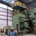
1. X-Ray Tube Support Boom is manufactured of tubular steel. The height of the
boom is adjusted for various pipe diameters manually at the operator control panel. The x-ray tube will be mounted at the end of the boom. The high voltage cable and cooling hoses will be connected from x- ray tube at the end of boom, through the
inside of the boom to the high voltage generator and cooling system located at the base of boom.
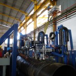
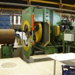
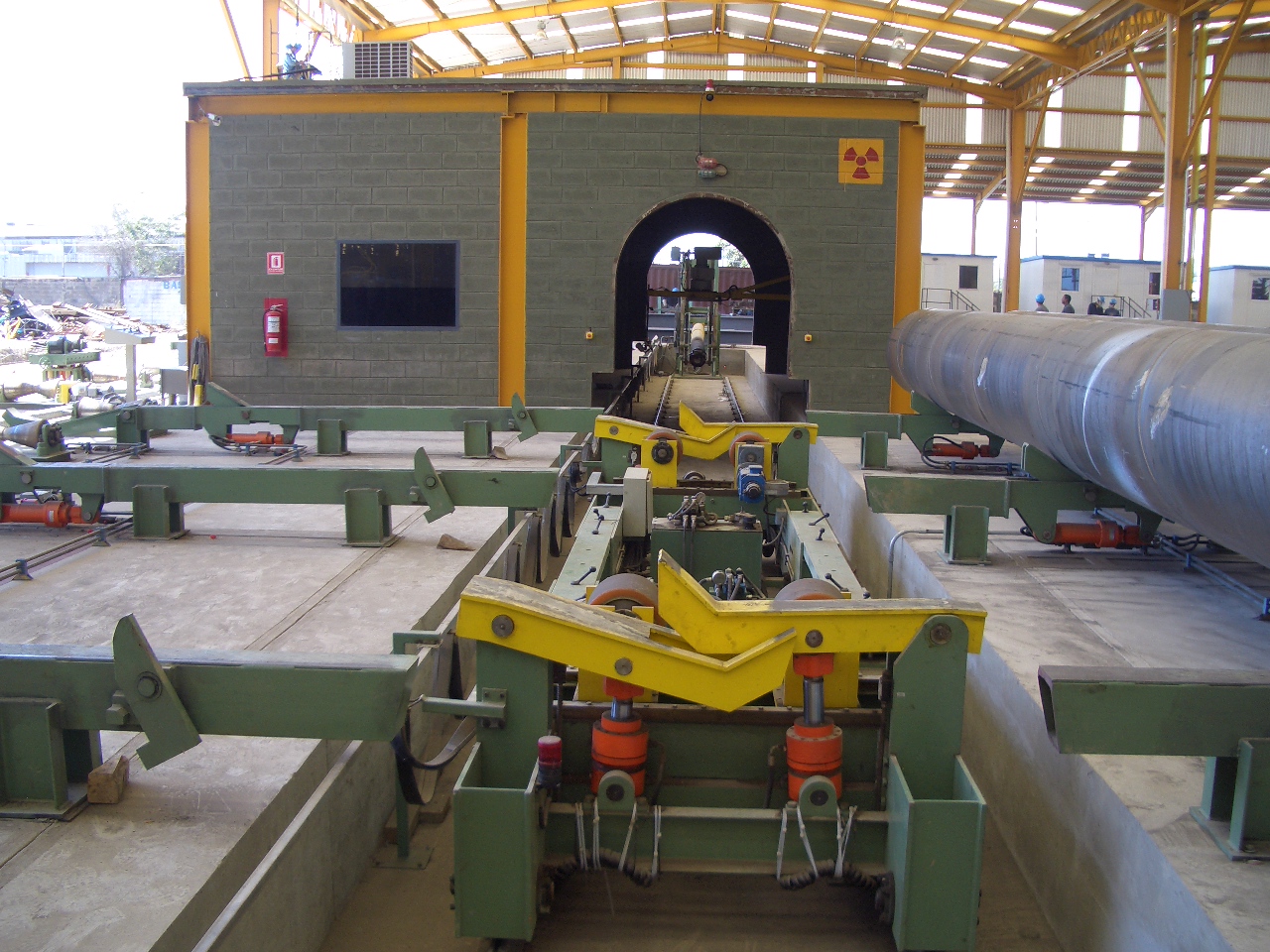
2. Pipe Cart carries the pipe from the pipe rack and moves along the rail to the test
position and returns the pipe to pipe rack again. Pipe cart provides linear movement
and rotation of the pipe. The combination of linear movement and rotation gives spiral movement to pipe to keep the weld position between x-ray and intensifier tubes correct during inspection.
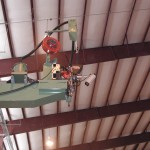
3. Image Intensifier Tower
Carries image intensifier and CCD video camera. The height of the tower can be adjusted manually at the operator control panel. The tower also carries the paint spray system to allow the operator to mark the pipe for defects.
4. X-Ray Components:
The High Voltage Generator supplies high voltage and current for x-ray tube by converting the voltage from the power supply. The x-ray voltage can be adjusted continuously for any value needed.
The metal ceramic X-Ray Tube is connected to the high voltage generator by a high tension cable.
The microprocessor Control Unit is installed in the operator control desk.
The kV, mA, warm-up can be controlled by control unit containing push buttons, potentiometers, signal lamps and digital display.
Cooling System has cooler and pump used for water circulation between x-ray tube and cooler via hoses.
5. Imaging System:
X-Ray images are converted into visible images by Image Intensifier Tube. The high resolution CCD Video Camera is coupled to the image intensifier tube to pick up the visible image. The visible image is displayed by a high resolution 14” Video Monitor. Digital Image Processor improves the quality of video image by using processing functions such as image integration, contrast, brightness, addition, subtraction, and noise reducing.
Real time images are stored by digital or VHS Video Record System. The image on the monitor can be printed on thermal paper by Hard Copy Printer.
6. Operator Control Desk has all necessary pushbuttons and joysticks for operating the system.
INITIAL ADJUSTMENT AND INSPECTION PROCESS
First, the gap between pipe turning rolls on the pipe cart is adjusted according to pipe diameter to be inspected before taking the pipes from pipe rack at the plant.
Initially, the pipe is taken onto pipe cart from pipe rack. Then the height of the x-ray tube support boom is adjusted to the correct position before entering the boom insideof the pipe for large diameter – single wall technique or respectively below the pipe for small diameter – double wall technique. Later, image intensifier tube is positioned to the opposite of the x-ray tube. Linear movement of pipe cart and pipe rotation on pipe cart moves pipe spirally parallel to the x-ray support boom. Due to relative movement of the x-ray and image intensifier tube, the x-ray tube moves into the pipe or respectively below the pipe and follows the weld seam for inspection. In order to start the inspection process, the pipe is moved spirally until the weld comes into position between x-ray tube and image intensifier tube. After this initial position, automatic weld following and inspection can be started in accordance with movement and inspection parameters previously determined.
The operator can stop the spiral scan at any time during automatic inspection to evaluate an indication and use image processing for more sensitive evaluation.
The automatic scan can be restarted to continue the scan from position where previously stopped. After the full length of weld has been inspected, the pipe cart is moved back to the start position so the pipe can be moved back to the pipe racks.