Relevant Background Information
Relevant Background Information
Mill Design
Pacific Roller Die (PRD) sold its first helical lockseam corrugated metal pipe mill in 1961. The D-4 models of that time were large, heavy, and powerful. As far as we know, all of them are still running.
In the mid-1960s PRD introduced the model D-5 design, which was even larger, heavier, and more powerful. These are still considered the best machines ever made for full-time processing of heavy gauge steel sheet.
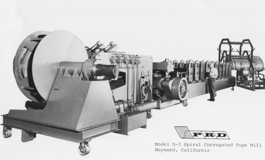
The PRD D-6 model was introduced in 1967 and quickly became the most popular pipe mill in the industry. This model can be built with the same performance specifications as the older models but it is smaller, lighter, more versatile, and less expensive. Today, with incorporating recent technological improvements and through decades of experience in manufacturing, the PRD D-6 mill is the leader in corrugating metal pipe.
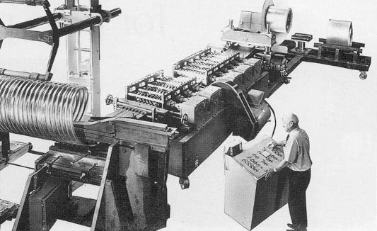
EQUIPMENT DESCRIPTIONS OF THE PRD SPIRAL CORRUGATED PIPE MACHINE MODEL D-6 AND SUPPORT MACHINERY
Optional Mill Equipment:
- Coil Rack and Buggy
- Coil Peeler with Pinch Rolls and Straightening Rolls
- Metal Strip Joiner and Shear
- Pipe Support Frames
- Digital Control System
- Enhanced Safety Package
Optional Supplementary Equipment:
- Double-Ended Recorrugating System
- In-Line Perforator/Corrugated Sheet Shearing System
- Fabricating Turning Rolls
- Yard Saw
- Arching Machine
- Hugger Band Machine
The standard D6 base model includes:
- The Coil Reel Uncoiler with the Helix Angle Drive,
- The Rolling Mill with Guide Stands
- The Pipe Forming and Spiraling Apparatus (“3-Roll”)
- One set, customer specified tooling profile
- The Automatic Cut-Off Saw
- The Runout and Dump System
- All electrical motors and wiring
Machinery Information
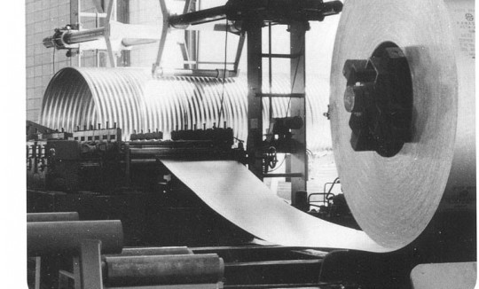
Coil Reel Uncoiler
The standard coil reel is a hydraulically expandable type with a capacity of 20,000 lbs. and a maximum width of 36 inches. Fabricated of steel weldments and precision machined construction is provided. The reel utilizes a hydraulic expanding system and operates in the bore of the coils. Expansion and contraction of the coil support leaf pads is provided through mechanical linkage hydraulically activated.
The reel spindles are mounted in anti-friction bearings at the front and rear of the base housing. Back tension is controlled through an adjustable drag brake.
Coil Rack and Buggy
Heavy-duty rails provide for coil (2) pre-load storage. A hydraulic lift buggy travels under the rack, picks up a coil and places the coil onto the uncoiler mandrel. The coil buggy is moved by a chain drive horizontally along the uncoiler frame (coil rack frame) to position the coil on the uncoiler leaves. One of the coil buggy rolls is driven by a hydraulic motor and is used as a ‘snubber’ to unwind the coil (if equipped). This equipment is provided to assist in material handling, improve coil change time, and minimize dependence upon crane service.
Helix Angle Drive
This unit is located beneath the base of frame and moves the entire mill around the pivot point as indicated by the diameter of the pipe to be produced. It is driven by a separate drive and controlled by a push button located on the operator’s console.
Coil Peeler with Pinch Rolls and Straighting Rolls
The Peeler is mounted over the Pinch Rolls on the side frame. The Peeler blade can move in and out by a pair of hydraulic cylinders, controlled by manual valve and it pivots around the tie bar by hydraulic cylinder, controlled by manual valve. It allows operator to peel, break and guide the leading edge to the Pinch Rolls. After the Coil Buggy Rolls drive the leading edge through the Pinch Rolls, the Pinch Rolls are used to drive the leading edge through Straightener Rolls and Shear up to the Coil Joiner Table where the coil ends are joined. This optional feature is ordered by those manufacturers who plan to run heavy gauge coils frequently. PRD offers two different designs.
Metal Strip Joiner and Shear
The function of the Strip Joiner and Shear system is to join the trailing end of an outgoing coil to the leading end of an incoming coil. The cutting-off operation is done with the Shear. The shear trims both the trailing end of the old coil and the entering edge of the new coil. After the two strip ends have been squared they are butted together over the copper weld backup bar located under the welder clamp. The two clamps are actuated hydraulically and secured manually to clamp the strip edges for manual welding. To obtain an acceptable, continuous strip, both ends must be clean, parallel to each other and perpendicular (square) to the edge of the strip. A complete strip joining system is provided which consists of adjustable support rolls, two-post hydraulic pull-down shear, hydraulic hold-down weld clamps, copper back-up bar, and an operator’s control panel.
Guide Stands
The separate horizontal roll stand is provided on the entrance and exit end of the mill to provide horizontal control of the strip as it passes through the mill. This includes adjustable side rolls, which move out from centerline of the strip.
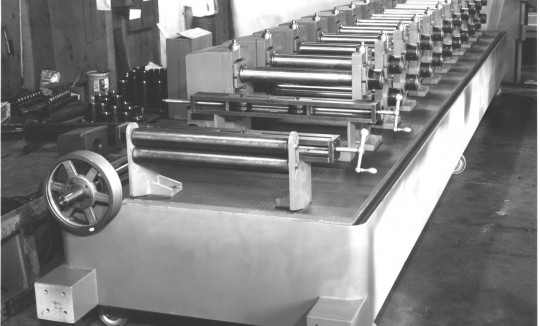
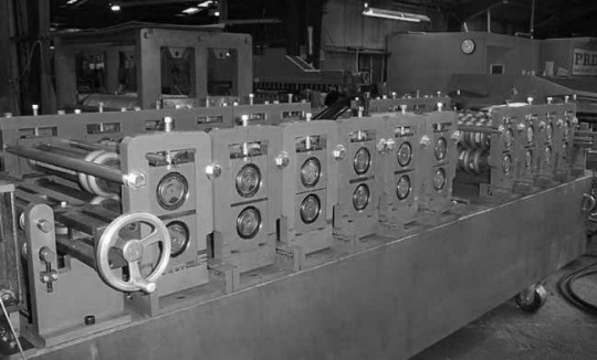
Rolling Mill
A complete assembly consisting of tooling stands driven from totally enclosed gearbox units. Double enveloping gear sets with large alloy bronze gear and pinion transmit power to the top and bottom tooling stands. All gears run in an oil bath.
Tooling stands include adjustable upper spindles and fixed lower spindles made from alloy steel, heat treated and ground. Minimum spindle diameter is 3 ½”.
The outboard bearing stands are made of steel weldments and/or ductile cast iron. The spindles are supported in anti-friction sealed bearings.
The base is a fabricated steel weldment, fabricated to include a tank and trough for lubricant handling. Strip lubrication system includes applicator, pump, and reservoir.
Pipe Forming and Spiraling Apparatus
The Pipe Forming and Spiraling Apparatus will often be referred to as the Three Roll for its basic design of using three rows of rolls for the function of turning the formed sheet up into spiral pipe. This unit is used to continuously up-curve the corrugated strip section into a right hand lead corrugated tube and then completely closes the preformed lock joint. The apparatus is supplied with an internal forming mandrel with lead, buttress and mandrel rolls for corrugation configurations to be supplied.
All mandrel, lead and buttress rolls are adjustable in order to provide correct angular alignment with the corrugated sheet and still provide exact parallel center of the spacing.
The three roll forming rolls are supported in steel yokes and all forming roll sets are locked together. Forming rolls are alloy steel, heat treated and ground and supported in a row of sealed ball bearings. Adjustment of the third roll in the unit is made manually.
The mandrel is positively attached to the weldment structure with fasteners and/or a hydraulically activated tilting mechanism. In conjunction with the mandrel is a set of automatic pressure compensated seaming rolls providing vertical adjustment of the lockseam relative to the neutral axis of the corrugation. Lockseam closing is accomplished in one pass with this pressure compensating hydraulically adjustable pressure roll system.
The pipe forming apparatus contains a connecting pin to provide continual attachment to the pivoting roll forming mill. The three roll system is aligned at installation to feed outgoing pipe along the centerline of the later cut-off and runout equipment.
Tooling
All the necessary roller dies, spacers, lock forming and setting rolls and forming mandrels for the corrugation configuration specified will be provided.
Corrugating rolls are made from high grade alloy steel suitable to roller dies. The rolls are heat treated and ground. Lock forming pressure rolls are made from high grade alloy steel, machined, heat treated and ground as necessary. Lock forming rolls have identification grooves.
Pipe Support Frame
A pipe support system with hold down rollers is optional equipment used to stabilize the pipe during the lock seaming and flying saw cut-off operation. (Standard equipment is a simple chain wrap.) This set of rollers applies counter pressure to the top and sides of the pipe while the pipe is being formed and does an excellent job of controlling the pipe as it leaves the spiraling apparatus and the saw blade is risen into the pipe.
Automatic Cut-Off Saw
A flying friction type saw will cut pipe sizes from the minimum to maximum diameter and gauge range specified. The saw blade is raised into the pipe by a hydraulic cylinder. The sawing unit then saws the pipe in synchronization with the output speeds of the pipe. The rotation of the pipe into the saw unit provides complete circumferential cut-off. Pipe cut-off is complete in 1 ¼ revolutions of the pipe. Upon completion of the cut-off, the saw blade is lowered from the cutting position. The saw unit then returns to rest position ready for another cycle. The saw blade is allowed to float in each direction from its centerline starting position during the cutting cycle. This is done in order that fractional speed changes throughout the line operation, if they occur, do not affect the sawing operation with undue pressure against the blade.
A water spray coolant system for cooling the cut-off saw blade will be included in this unit. This unit will facilitate the ease of cutting, will decrease the amount of burr on the pipe, and will also extend the life of the saw blade between sharpenings.
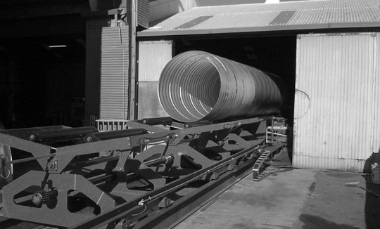
Runout and Dump Systems
A runout system is provided for supporting the outgoing pipe before and after cut-off. When the cut-off cycle is completed, the system transfers and dumps the pipe in right or left pre-selected direction from the runout centerline.
The pipe support rolls are adjustable to accept 6” minimum diameter tube to maximum diameter tube of 144”.
A length trigger is mounted down the runout centerline and is manually adjusted. Standard systems have (4) carts and accommodate pipe lengths up to 40 foot. Optional is a (6) cart system to accommodate up to 60 foot pipe sections.
Electrical
ll necessary motors machine mounted, motor starters, operator’s console, hydraulic pumps and motors, cycle control limit switches and speed sensing devices are provided. The main mill is powered by an A.C., 3-phase, 60 Hz, 440-volt motor 75 H.P. depending on maximum machine capacity unless otherwise specified.
The saw motor is 125 H.P. depending upon machine capacity and is also 440 volt, 3-phase, 60 Hz, A.C. unless otherwise specified.
All other motors are A.C., suitable for 3-phase, 60 Hz, and 440-volt operation unless otherwise specified.
An optional Digital Control System – gives the operators the ability to monitor all the working parts of the system from a single control panel and make fine adjustments manually or by automatic control.
Double-End Re-Corrugating System
This equipment is installed in position to receive the formed pipe after leaving the run-out tables. Typically transfer rails will distance the recorrugator and the runout to allow production of pipes to accumulate in front of the recorrugator. The system accepts the formed pipe and adds reformed perpendicular corrugations on both ends of the pipe to allow for clean coupling of pipe segments in the field. It consists of two dump buggies, one fixed end recorrugator and one moving/adjustable end recorrugator to accommodate 10ft. to 40ft. pipe lengths. Includes 1/2” 2.66” segmented dies for four corrugations on each end, hydraulically adjusted back-up support rolls, adjustable pipe support rolls, small diameter support rolls and has a specified capacity of metal thickness from 18 through 10 gauge.
In-Line Perforator/Corrugated Sheet Shearing System
One machine adaptable for two functions; punching holes for perforated pipe and shearing corrugated sheets for siding and other applications. (1) For manufacturing partial or full circle perforated pipe, the mechanical high-speed pull-down press with punch tooling is positioned between the uncoiler and roll former to punch holes prior to corrugating the sheet and forming pipe. A flying die set is accelerated by the strip movement and returned by an air cylinder to await the next cycle. The hole diameter is punched in accordance with current AASHO perforated pipe standards. The hole diameters from 3/16” inch to 1 3/4” are available depending on product being perforated.
Tooling will be quoted in conformance to customer or market requirements.
(2) For manufacturing cut-to length sheets, the mechanical high-speed pull-down press with shear blade tooling is positioned after the pipe forming and spiraling apparatus (three roll). The three roll is opened and now acts as guide rolls prior to the sheet cut off. Cut-to-length sheets are manufactured for use as coupling band stock, sheets for annular riveted pipe and roofing/siding building sheets. An electronic counter at the roll former signals the cut-off sequence for desired sheet lengths. Cut sheets are then rolled off and gathered by a sheet collection table. Shear blades and sheet edge forming dies are required for each profile to be used.
Enhanced Safety Package
Using the latest is industrial grade safety electronics; PRD Company has designed a comprehensive safety package to address the potential hazards associate with operation of industrial manufacturing machinery. First implemented for use in Europe it received complete CE safety conformity and has since been used with great acceptance on recent domestic installations. A full perimeter light guard around the Uncoiler, Coil Rack, and Peeler/Straightener machinery, a light curtain above the Roll Former tooling, and hard guards in numerous locations are some of the items included in the package.
Yard Saw
Many CMP production facilities utilize a Yard Saw Station for cutting culvert pipes to specific lengths per customer requirements. A complete packaged Yard Saw is available through PRD Company for this purpose. The benefit of having a complete off-line station for cutting pipe to length is that full production of standard length pipes can be run off the mill with out interruption and stored in inventory, then when a customer orders smaller lengths the yard saw accommodates this. However, if smaller length pipes are necessary and no yard saw station is installed on-site a worker can torch through pipes, but this is only effective for limited quantity.
Arching Machine
Another piece of equipment to consider at this point is an Arching Machine for manufacturing Arched Pipe. This type of pipe is used for installation where wide spans (width of pipe) and short rise (height of pipe) is required. PRD Company offers two styles of Arching Machines: hydraulically operated internal expanders and chain wrap cinching formers. The cinch type external arching machine uses material thickness up to 8 gauge and has a diameter range from 15” to 72” for a large range of project types.
Hugger Band Machine
Another piece of equipment to consider at this point is an Arching Machine for manufacturing Arched Pipe. This type of pipe is used for installation where wide spans (width of pipe) and short rise (height of pipe) is required. PRD Company offers two styles of Arching Machines: hydraulically operated internal expanders and chain wrap cinching formers. The cinch type external arching machine uses material thickness up to 8 gauge and has a diameter range from 15” to 72” for a large range of project types.