OFF-LINE ULTRASONIC TEST SYSTEM
CONTENTS
1 – ULTRASONIC TEST EVALUATION METHOD
2 – OFF-LINE WELD TEST
3 – LASER SEAM TRACKING FOR OFF-LINE AND ON-LINE WELD TEST
ULTRASONIC TEST EVALUATION METHOD
1.1. Weld Inspection:
The test is carried out according to the pulse-echo method for longitudinal weld defects and through-transmission method for transverse weld defects and also for coupling and performance check of the probes. Angle beam probes are used for longitudinal and transverse weld defects.
1.1.1. Longitudinal Weld Defect:
Two angle beam probes are facing each other and operate in pulse-echo mode for defects and in a through transmission mode for coupling and performance check of the probes.
1.1.2. Transverse Weld Defect:
Two angle beam probes operate in through-transmission mode. The transmitting probe transmits the sound beam at an angle of 45 degrees to the weld. If a transverse defect exists, the sound beam is reflected from there and received by the second probe facing the first one.
1.2. H.A.Z. Defect:
Laminar defects in Heat Affected Zone are detected by immersion straight beam probes. The immersion probes are coupled via water column. The probes operate in pulse-echo mode. The test is performed by means of evaluation between interface echo and first back wall echo. The possible time variation in water column is compensated by the echo start system.
1.3. Body Lamination:
Two or four twin crystal probes are used in pulse-echo mode for pipes to be inspected for laminations in base metal.
The probes are moved back and forward on pipe body between weld seams by the oscillating device. The oscillating device is placed after external S.A.W. station on runout of pipe mill. The coupling between probes and pipe surface is supplied by water gap. Lamination can be detected by evaluation gate to be positioned between interface echo and
first back wall echo or between first and second back wall echo.
OFF-LINE WELD TEST
2.1. Test Principle:
The pipes are carried individually on pipe cart. The combination of axial movement of the pipe cart and circumferential turning of the pipe on pipe cart passes the pipes according to spiral angle of weld seam through the testing line.
The probes are lowered to the top of the pipe by means of sensor until reaching the set-up distance between pipe surface and probe mechanism.
The probes can be positioned on the end of pipe for alignment of the weld seam center to probe mechanism and receiving proper water coupling between pipe surface and probes. Therefore, untested weld seam at the end of pipe will be around 100 – 200 mm.
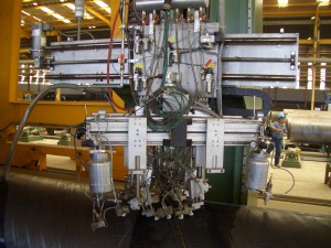
2.2. Probe Arrangement:
Total of eight probes are located on sides of weld seam as follows:
Probe 1 – Longitudinal weld defect
Probe 2 – Longitudinal weld defect
Function Test (Coupling Check) between Probe 1 and Probe 2
Probe 3 / Probe 4 – Transverse weld defect
Probe 5 – Function Test (Coupling Check) for Probe 4
Probe 6 – Function Test (Coupling Check) for Probe 3
Probe 7 – H.A.Z. Test
Probe 8 – H.A.Z. Test
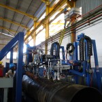
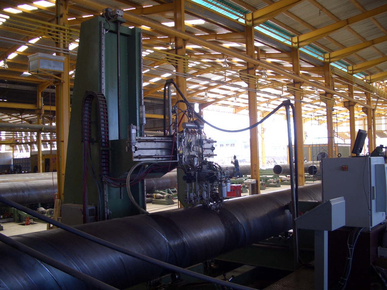
2.3. System Description:
Two parallel rails are mounted on the floor. There are two carts on the rails to carry and move the pipes. Two carts are connected by steel bars. The distance between carts can be manually adjusted according to the pipe length to be inspected. Each pipe cart is equipped
with four wheels. Two wheels of the first cart are driven by three phase servomotor (or DC motor) for sensitive linear movement of the carts on rails. The second cart has idle wheels. Each pipe cart has two rollers for rotating the pipe. One of the rollers is driven by three phase servomotor. The distance between rollers on each cart can be manually adjusted according to pipe diameter. The pipe is synchronously moved linearly by cart and rotated by rollers. As a result, spiral movement can be obtained to follow the weld seam. The loading/discharging of the pipes from/to pipe racks to/from pipe carts is done by kick out/let down arms mounted on carts. There is a hydraulic unit for powering the hydraulic cylinders of the kick out and the let-down arms. Cantilever lifting frame is mounted on the floor and carries the probe holder mechanism for adjusting the height of the probe holder mechanism according to the pipe diameter to be tested.
2.4. Test System Components
4.1. Evaluation electronics (8 Channels) including cabinet and air condition mounted on the top of the cabinet.
4.2. Probe holders and Weld Seam Tracking Mechanism
4.3. Manual weld seam tracking system (camera, monitor, laser pointer, joystick)
4.4. Cantilever lifting frame
4.5. Water unit for coupling
4.6. Paint marking system – 2 units (one for weld defect and one for H.A.Z. defect)
paint spray gun
paint reservoir
solenoid valve
gun fixing rod and connector
4.7. Probe holders and probes angle beam probes and holders – 6 units H.A.Z. immersion probes and holders – 2 units
4.8. Pipe Handling System – Pipe carts
4.9. Operator control panel for test mechanism and pipe handling system.
LASER SEAM TRACKING FOR OFF-LINE AND ON-LINE WELD TEST
The distance between weld seam center and probe index point must be constant for proper evaluation during ultrasonic test process. Therefore, the deviation of the distance shall be corrected by shifting the probe holders mechanism. Laser weld seam tracking system sends signal to the test mechanism, in case there is deviation on set-up distance between weld seam center and probe index point.