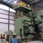
PIPE END GROOVING MACHINE (PEGM)
The system consists of the following components:
-Grooving System
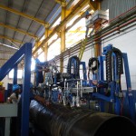
-Pipe supporting System
-Kick-in + Kick-out system
-Hydraulic system
-OP and MCC panels.
The system is delivered with one set of dies according to requested material thickness and profile.
Technical Data:
Maximum Pipe diameter specifically in this system is: 72”
Wall thickness range: from 0.1345″ to 0.5”
Grooving power: 55 kW DC./Hydraulic power: 11 kW AC.
Diameter of Inner Roll: 400 mm./Diameter of Outer Roll: 600 mm.
Stroke of the machine towards the pipe: 500 mm./Radial stroke: 100 mm.
Material of the dies: 1.2379 (160 CrMoV 12)
Calculated grooving force: 250 m.ton FOR X 60 0.5”
Designed grooving force: max. 300 metric tons
Weights
Grooving System: 35 metric tons
Pipe Support rolls + kicking system: 11 metric tons
TOTAL WEIGHT OF THE SYSTEM: 46 metric tons
EQUIPMENT DESCRIPTION
- Pipe is fed through the rails coming from Pipe End Expander and when it is on the center of EGM arms will take the pipe slowly on the specially designed rollers, which are idle but support the pipe while it rotates during grooving process. The center distance of those rollers are adjusted automatically according to the pipe diameter entered from Screen Panel by the operator. The reason for this adjustment to keep the bottom level of the different diameter pipes approximately at the same level.
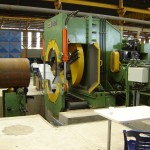
- While the pipe lies on the rollers, EGM starts moving toward the pipe so that it takes the pipe in between two dies.
- Then the inner body, which holds the outer die, moves towards the pipe. This approach is done by servo controlled hydraulic system and measured by linear encoder.
- After lower die presses to the pipe with a certain min. force the inner die starts rotating, while the pressure of the grooving cylinder increases so that grooving process continues up to the pre-entered value which is measured by linear encoder system and monitored on the screen panel by the help of PLC.
- After grooving finishes, inner die stops and outer die goes down.
- One of the most sophisticated parts of this machine is that dies copy the pipe surface.
This is necessary because the weight of large diameter pipes causes them to distort out of round, preventing them from rotating smoothly on the support rolls during the grooving process. Copying the side of the pipe prevents the problem of damage to the groove. The machine consists of three main bodies to attain this very sensitive copying system.- Main Outer Body, which holds all parts.
- First inner body slides on the tip of a very sensitive servo-controlled hydraulic cylinder, which moves the first inner body up and down in opposition to the incoming force from the side of the pipe
- Grooving die is controlled by the second inner body, which is contained within the first inner body but able to move independently.